Difference between revisions of "Observer Nodes"
| Line 5: | Line 5: | ||
Each observer node is currently connected to two popular [[Supported Platforms|target platforms]] (a Tmote Sky mote and an nRF52840 development kit) using a special [[Media:Observer_mux.png|multiplexer unit]]. A set of slides giving a brief overview of D-Cube's capabilities and architecture can be found [http://www.carloalbertoboano.com/documents/D-Cube_overview.pdf here]. For more information, please refer to the [[Publications|publications page]]. | Each observer node is currently connected to two popular [[Supported Platforms|target platforms]] (a Tmote Sky mote and an nRF52840 development kit) using a special [[Media:Observer_mux.png|multiplexer unit]]. A set of slides giving a brief overview of D-Cube's capabilities and architecture can be found [http://www.carloalbertoboano.com/documents/D-Cube_overview.pdf here]. For more information, please refer to the [[Publications|publications page]]. | ||
|[[File:empty.png|left|175px]] | |[[File:empty.png|left|175px]] | ||
| − | |[[File:observers_architecture.png| | + | |[[File:observers_architecture.png|2725px|right]] |
|} | |} | ||
Revision as of 11:21, 10 November 2019
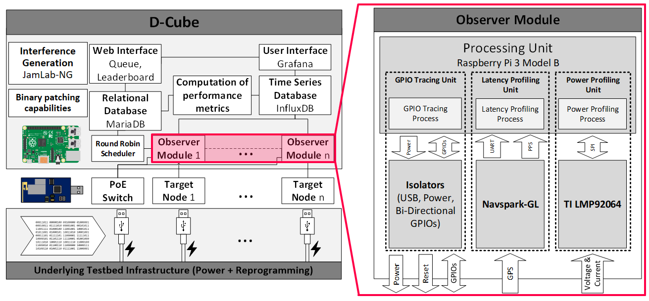
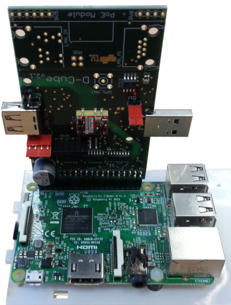
| D-Cube makes use of several Raspberry Pi 3 nodes, each connected to a custom add-on card, as unobtrusive observer nodes to measure the reliability, latency, and energy-efficiency of IoT protocols running on a given target platform.
Each observer, which is powered by PoE and connected via Ethernet to a central server, is completely agnostic to the hardware platform chosen as a target, as long as the latter can be connected via USB to the custom add-on card. Each observer node is currently connected to two popular target platforms (a Tmote Sky mote and an nRF52840 development kit) using a special multiplexer unit. A set of slides giving a brief overview of D-Cube's capabilities and architecture can be found here. For more information, please refer to the publications page. |
| The custom add-on card connected to the Raspberry Pi 3 embeds a power and latency profiling unit, as well as a GPIO tracing unit. The power profiling unit captures voltage and current using a 125 kHz simultaneous-sampling 12-bit current and voltage analog-to-digital converter. The use of optocouplers as isolation layer between the GPIO pins of the target node and the ones of the observer module ensures unbiased energy measurements.
The GPIO tracing and latency profiling units allow simultaneous tracing and actuation of up to 8 GPIO pins per target platform. Observer nodes equipped with a GPS unit can generate precise timestamps for externally triggered events. Nodes without direct GPS connectivity can synchronize to the rest of the network using NTP with a typical accuracy well below 10μs. Target nodes can be individually powered on/off in software, hence allowing to control the network density and to emulate node failures (e.g., due to an early battery depletion) by software. The hardware design of the add-on card is openly available on GitHub. |
Under construction.


